The current page has been visited 36119 times.
Visitors today: 9
Hits to all pages: 10572961
Server-Time: 14:41
2026-01-24
|
HD-motor
experimental driving circuit

|
The motors which drive the platters within a harddrive, usually are synchronous motors. Those motors have several coils (usually 3), which are arranged in star- or delta-connection. To bring synchronous motors to life, special driving circuits are needed which generate the required moving magnetic field within the coils of the motor.
As I once again played around with killed harddrives, I had such a motor in my hands and decided to give it for the last time a spin.
|
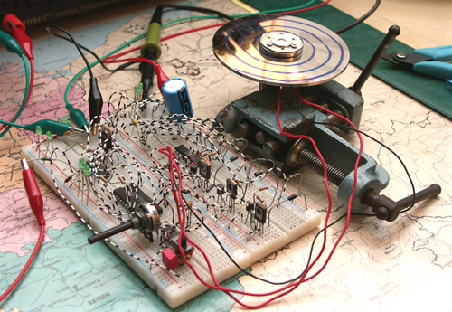
My motor is a version with 3 coils in delta-connection (3 connection wires). To power it, rotary current is required.
The simpliest way to create rotary current (which causes phase shifted, sinusoid coil currents) is to use a microcontroller with several PWM-units. In my case, I wanted to come along even simplier and decided to use square formed coil currents which are very easy to generate with a discrete program automat.
Because of that, the circuit consists of the following parts:
- clock generator
- binary counter
- binary decoder
- program generator
- 3 N/P-channel boosters
By using a discrete program generator, the output boosters are driven to generate a circular moving magnetic field within the synchronous motor. The circuit is primitive and neither has a feedback control nor a automatic start-up - but this wasn't the goal of this experiment, anyway. The only goal was to have a rotating motor - as you can see in the video, this works very well.
|
|


