The current page has been visited 25504 times.
Visitors today: 3
Hits to all pages: 8163769
Server-Time: 06:08
2024-04-19
|
How to reproduce the CPU-board...
If you want to reproduce this small helper-board, then go on reading this page... ;)
First off all: this board is not perfect!
It is more or less just a help for connecting the 0.65mm pitched pins to regular 2.54mm (1/10 inch)
sized prototype-boards.
There are still some wires to vero-wire by hand. This is because I didn't want to make a double-sided
PCB for this tiny thing...
If you want to use this layout, you have to print the image with the following dimensions:
88.9000 mm width
82.5500 mm height
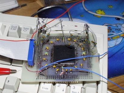
After having successfully made the PCB, you have to solder the CPU first and then solder on
each capacitor place a ceramic 100nF capacitor.
On the bottom side of the PCB you have to connect all the +3.3V sides of the capacitors together.
Same with the GND sides.
Finally, you have to connect the +3.3V sides with a small wire to the two +3.3V pins at the upper and lower
layout border.
Two pictures will be much more helpful that thousand words (click to enlarge!):
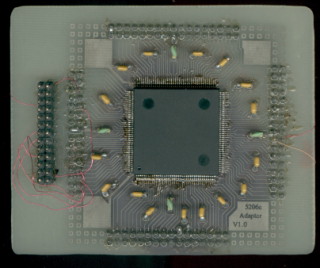
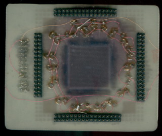
Questions? Please have a close look at the higher resolution scans.
Still questions? Do this again! And have also a look at the 5206e pinout table!
You have still questions? Well, then don't hesitate to write an eMail to me! :)
Now you surely want to have the PCB layout?
Well, here is it:
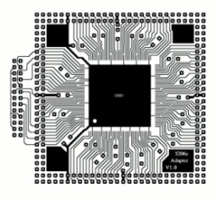
(click for the full GIF image!)
|
|
|


